 My Williams Phoenix Pinball machine uses (roughly) 200+ Watts of power when on. Translated: Some components can get very hot. Especially if the pinball is left on 24/7 as it may be at an arcade or a bar.
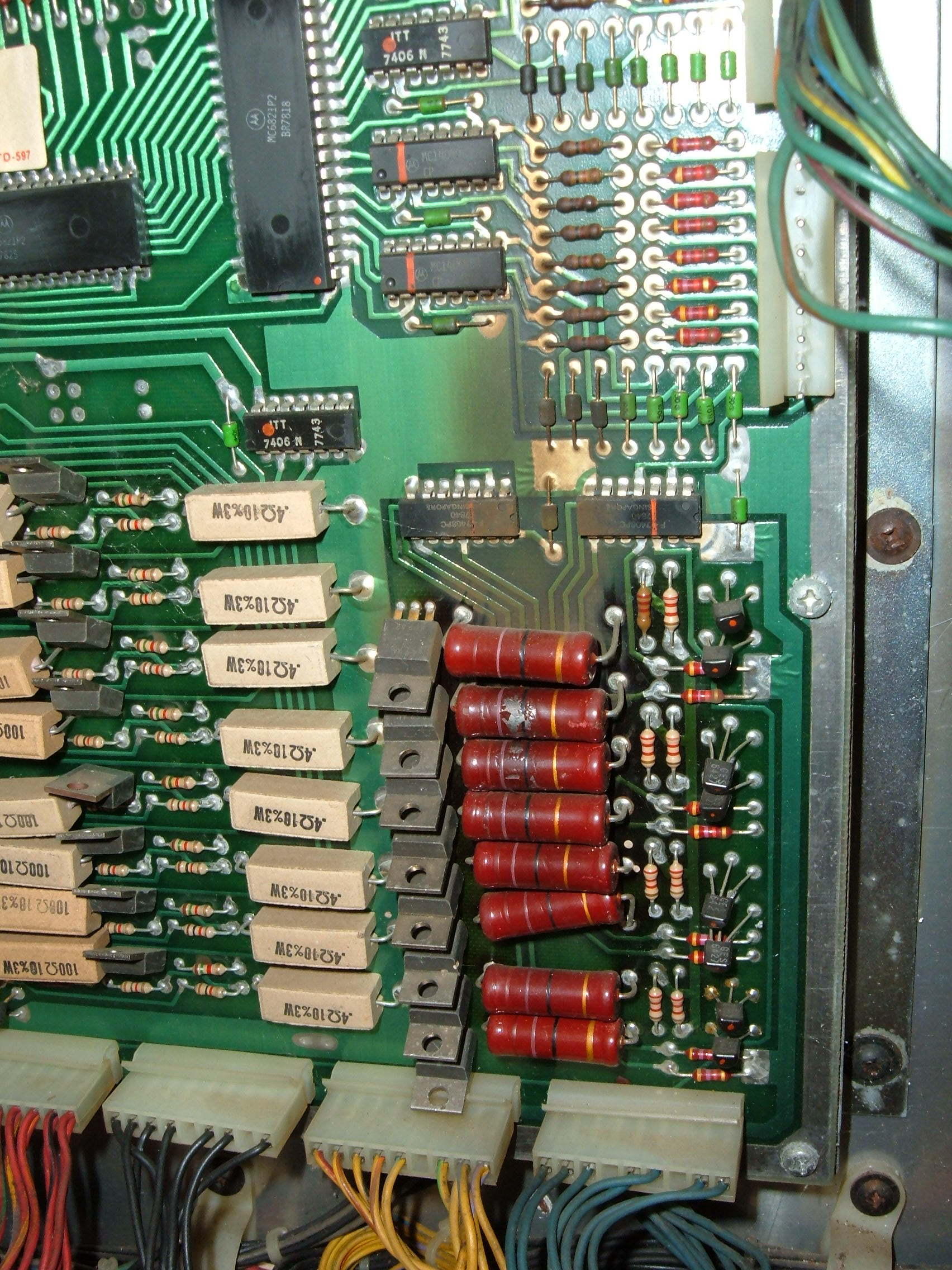
To the right is a photo of some General Illumination power resistors (click to enlarge). As burned up as they look, they still work and still measure their correct resistance values. Also you can see it started to burn up the components directly above them (which go to the Switch Matrix).
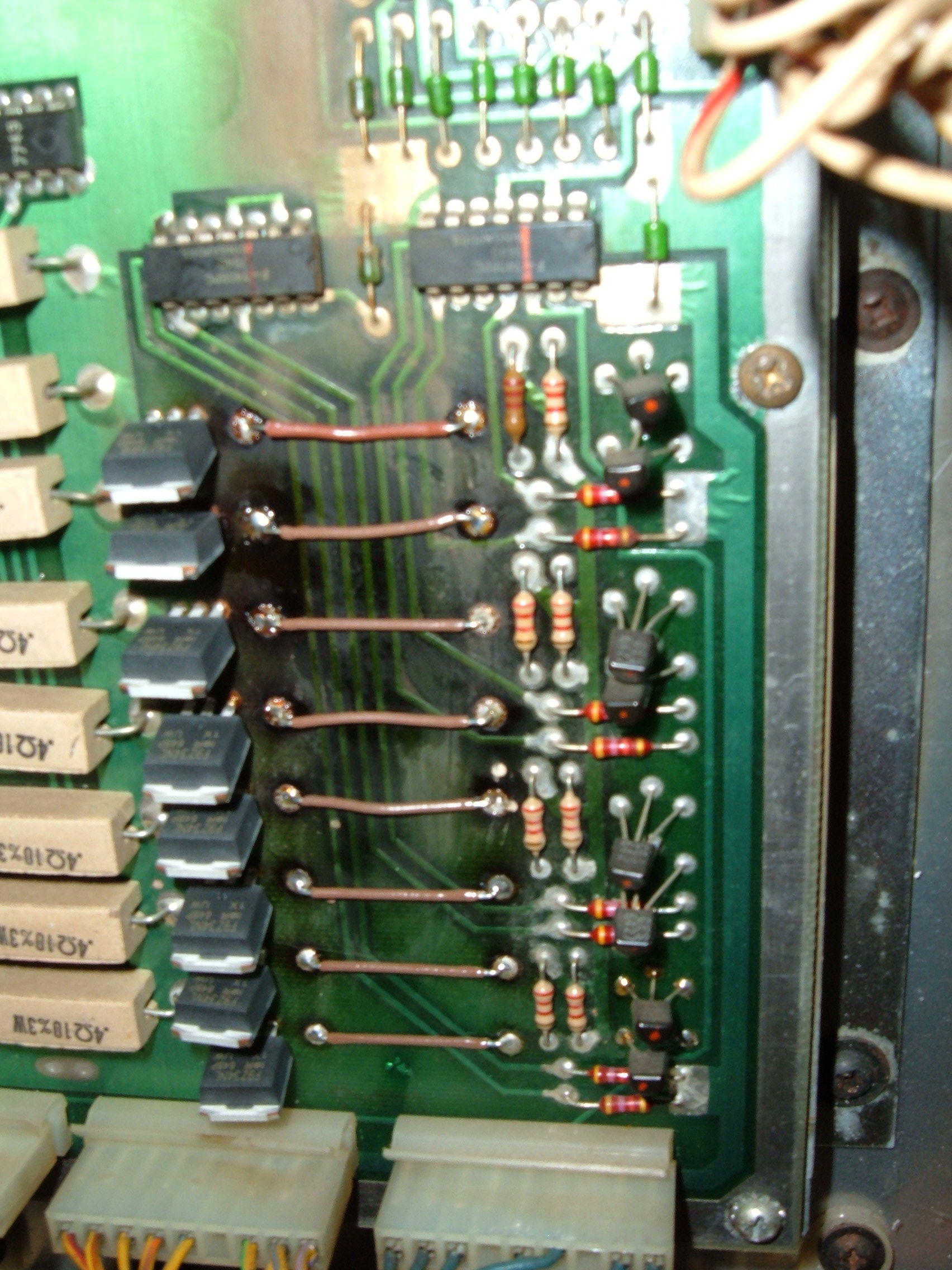
Pinrepair.com had a brief suggestion of instead of replacing those resistors with higher-wattage ones… or to simply replace those drivers right next to them with MOSFETs, and ditch the resistors with zero-ohm jumpers. Since I had to order some replacement driver-board transistors (and an IC to fix the switch matrix), I decided to just order the 55-volt, 19Amp MOSFETs from digi-key (IRF9Z34NLPBF-ND $1.935 each). Works great! Just need to clean the circuit board a little better (pictured left).
While I had the driver board out, I also had to do some repairs to the Switch Matrix. The night while I was diagnosing the Solenoid Fuses, in the middle of a “game”, I noticed that it stopped scoring points for half of the switches. It didn’t even register the end of the ball in play anymore!
The pinball’s switch matrix works just like any other keypad-style encoder: It puts out a voltage on the “colums” and checks the voltage back from the “rows”. The Switch Matrix has 8 Column Drives (only the first 6 are used) and 8 Row Inputs going to two connectors on the driver board. After unplugging those connectors, I put the CPU in “Switch Test Mode” (which confusingly more only shows the last 4 “stuck” switches). The fact that it showed stuck switches with the connectors unplugged ruled out any shorted wires in the playfield. So one by one, I manually short the rows & columns together while reading the Test’s ‘last-pressed-switch-number’. When I’m finished, I learn that all of rows 5 thru 8 are stuck active.
Some schematics show that rows 5 thru 8 are all inverted by IC15 (visible in the power-resistor photo 2nd chip down from the top), an MN14049 Hex Inverter. Bringing up the datasheet of the chip to get the appropriate pins and testing with a multimeter shows the inverter is no longer inverting. 5 volts in and 5 volts out. Replaced it with an “MC14049UBCPGOS-ND” from digikey ($0.69). Worked like a charm.
Leave a Reply